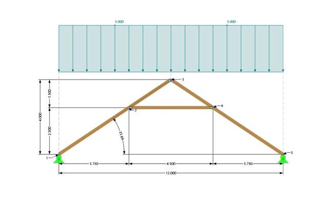
A collar beam roof with the selected geometry is compared in terms of its internal forces between the calculation using RFEM 6 and the manual calculation. In total, three load systems are analyzed.

A thin string is tensioned by an axial force. Determine the natural frequencies of the string.

A thin plate is fully fixed on the left end and loaded by uniform pressure on the top surface. Determine the maximum deflection. The aim of this example is to show that a surface of the surface stiffness type Without Membrane Tension behaves linearly under bending.

A simply supported beam is loaded by pure bending. Determine the critical load and corresponding load factor due to lateral buckling.

A thin circular ring of a rectangular cross-section is exposed to external pressure. Determine the critical load and corresponding load factor for in-plane buckling.

A curved beam consists of two beams with a rectangular cross-section. The horizontal beam is loaded by distributed loading. While neglecting self-weight, determine the maximum stress on the top surface of the horizontal beam.

A two‑story, single‑bay frame structure is subjected to earthquake loading. The modulus of elasticity and cross‑section of the frame beams are much larger than those of the columns, so the beams can be considered rigid. The elastic response spectrum is given by the standard SIA 261/1:2003. Neglecting self-weight and assuming the lumped masses are at the floor levels, determine the natural frequencies of the structure. For each frequency obtained, specify the standardized displacements of the floors as well as equivalent forces generated using the elastic response spectrum according to the standard SIA 261/1.2003.

The goal of this example is to demonstrate an irreversible process caused by friction. After the loading and unloading, the end-point is in a different position than where it was at the beginning. Determine the movement of the node in the X direction.

A cantilever from a rectangular cross-section is lying on an elastic Pasternak foundation and loaded by distributed loading. The image shows the calculation of the maximum deflection and maximum bending moment.

A steel cable or membrane with pins on both ends is loaded by distributed loading. Neglecting its self-weight, determine the maximum deflection of the structure using the large deformation analysis.

A cantilever from a rectangular cross-section is lying on an elastic Winkler foundation and loaded by distributed loading. The image shows the calculation of the maximum deflection and maximum bending moment.

A steel beam with a square cross-section is loaded with an axial force and distributed loading. The image shows the calculation of the maximum bending deflection and critical load factor according to the second-order analysis.

Determine the maximum deflection of a cube. The cube's lower side is fully fixed and the upper side is subjected to shear loading.