The structural analysis software RFEM 6 is the basis of a modular software system. The main program RFEM 6 is used to define structures, materials, and loads of planar and spatial structural systems consisting of plates, walls, shells, and members. The program also allows you to create combined structures as well as to model solid and contact elements.
RSTAB 9 is a powerful analysis and design software for 3D beam, frame, or truss structure calculations, reflecting the current state of the art and helping structural engineers meet requirements in modern civil engineering.
Do you often spend too long calculating cross-sections? Dlubal Software and the RSECTION stand-alone program facilitate your work by determining section properties of various cross-sections and performing a subsequent stress analysis.
Do you always know where the wind is blowing from? From the direction of innovation, of course! With RWIND 2, you have a program at your side that uses a digital wind tunnel for the numerical simulation of wind flows. The program simulates these flows around any building geometry and determines the wind loads on the surfaces.
Are you looking for an overview of snow load zones, wind zones, and seismic zones? Then you are in the right place. Use the Geo-Zone Tool to determine quickly and efficiently snow loads, wind speeds, and seismic data according to ASCE 7‑16 and other international standards.
Would you like to try out the capabilities of the Dlubal Software programs? You have the opportunity to do so! The free 90-day full version allows you to thoroughly test all our programs.
Saving Graphic Template
Once you have assigned the concrete material and activated the design properties in the member input dialog box, the display of the reinforcement layout for the selected member is available.
In the Display Reinforcement Layout window, you can proceed as follows. 1. Use the options in the menu bar to customize the display according to your preferences. 2. This configuration can send "Directly to a printer" as a template.3. When saving the template, it is stored globally and is also available for future models.
Multi Print of Reinforcement Layout for Selected Members
Use this graphic template to print the reinforcement of any members with a similarly formatted reinforcement layout in a multi print.
RFEM allows you to perform structural analysis and design of laminate and sandwich structures. The same applies to the cross-laminated timber. Stress and deflection analysis of laminate and sandwich surfaces is performed according to the laminate theory, taking into account the shear coupling.
Programs and Add-ons
RFEM is the main program that you can use to define the model and actions. You can model planar and spatial structures, consisting of plates, walls, shells, and members.
For the stress and deflection analysis, you need the Multilayer Surfaces add-on. It allows you to define and analyze layer structures.
Use the Timber Design add-on to also design the member supporting elements of the structure according to Eurocode 5 or ANSI/AWC NDS, for example.
Dynamic Analysis
If you need to perform a seismic or vibration analysis, the corresponding Dynamic Analysis add-ons are the perfect tools for determining natural frequencies and mode shapes, or for the analysis of external excitations.
In case of any questions about the Dlubal timber design solutions, our sales team will be happy to assist you.
If line hinges are to be defined on several boundary lines of surfaces at the same time, the following procedure is recommended:
Update: It is not necessary to click the "+" sign. After selecting a surface and the corresponding lines, you can simply select the next surface and the corresponding lines, and so on.
To create an imperfection based on a mode shape, the Structure Stability Add-on is required. In this way, mode shapes can be determined for a load case or a load combination based on its axial force state. The resulting mode shape can be selected and scaled after creating an imperfection case. The video shows the procedure.
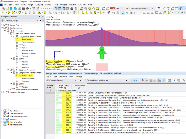
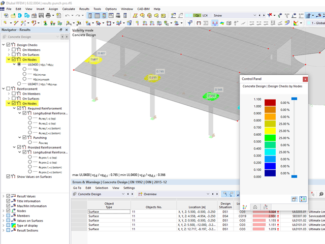
It can happen that all design checks are fulfilled for a particular member or set of members, but a "Not Covered Reinforcement" result is still output. See also Image 01 and Image 02.
The reason for this is that the distribution of the "Provided Reinforcement" on the upper and lower positions is generated from the rebar arrangement within the cross-section.
The rebars above the center of gravity are assigned to the "upper position" and the rebars below the center of gravity are assigned to the "lower position". This means that the distribution of the "Provided Reinforcement" does not consider the actual distribution of the zero line within the cross-section, and checks which rebar is actually in the tension zone.
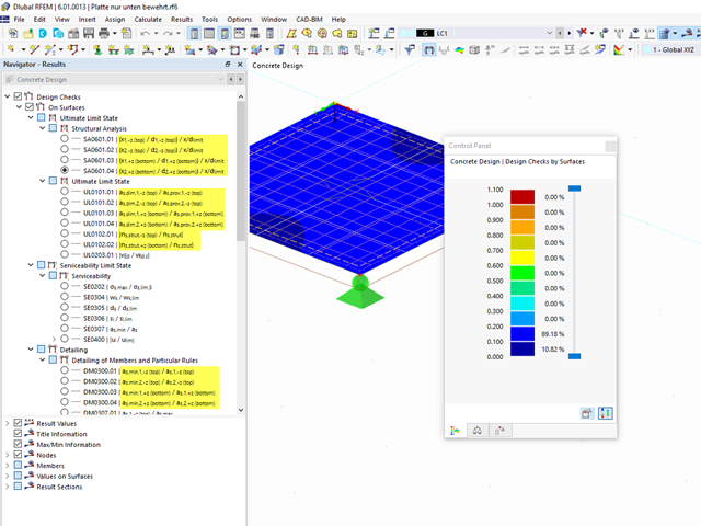
However, the actual distribution of the zero line within the cross-section is checked during the design. Thus, the rebars that have been geometrically assigned to the "lower reinforcement" (the provided reinforcement distribution) can be mathematically assigned to the tension reinforcement. This can be seen in Image 03. The rebars marked in red have been assigned geometrically to the lower reinforcement. However, the stress distribution within the cross-section shows that they are also subjected to tension and apply to the design checks accordingly. In the design, all members (marked in red and green in Image 03) are applied. Therefore, all the design checks are fulfilled at this location, although the distribution of the "Not Covered Reinforcement" suggests otherwise.
Yes, this is possible in RFEM 6.First, check whether there is a printer with the DIN A0 format available in the Windows control panel. If so, this printer is available in the printer settings in RFEM 6.
You can find an example with a printout report in the DIN A0 format under Downloads.
The punching results can also be found in the Results navigator.The results are divided into the design checks "On Nodes" and the reinforcement "On Nodes".The punching loads as well as the distribution of the shear forces at the critical perimeter (smoothed and unsmoothed) are the intermediate results of the design checks and are arranged accordingly in this part of the navigator.
No, this is not possible in the current state of development of RFEM 6.
See also the FAQ for RFEM 5 and RF‑CONCRETE Surfaces by clicking the link below.The design concept is currently structured similarly and is based on the reinforcement on the top and bottom sides.
Yes, you can.
To do this, open the settings for the "Concrete Design" add-on. You will find the setting here for switching from "mesh nodes" to "grid points".
Yes, the data are freely accessible. You can download the presentations and finished models by the speakers under Downloads below.