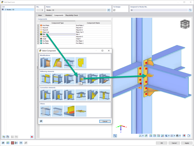
Using the "Rib" component, you can define any number of longitudinal ribs on a member plate. By defining a reference object, you can automatically specify welds on it.
The "Rib" component can also be arranged on circular hollow sections. Dafür wird zusätzlich die Vorgabe der Winkel zwischen den Rippen benötigt.
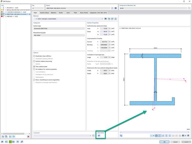
You can open the cross-sections in RSECTION using a direct connection, modify them there, and transfer them back to RFEM/RSTAB. Both RSECTION cross-sections and library cross-sections, with the exception of elliptical, semi-elliptical and virtual joists, can be opened and modified directly in RSECTION by clicking a button.
For example, you can thus adjust the reinforcement layout of user-defined RSECTION cross-sections directly in a local RSECTION environment in RFEM/RSTAB. This feature is currently only available for cross-sections with a uniform distribution type. The shear and longitudinal reinforcement defined for library cross-sections is not imported into RSECTION.

In the "Shear Reinforcement" tab, you can select the option "Cross-ties over free rebars with active selection in graphic". It allows you to arrange additional cross-ties on free rebars of the longitudinal reinforcement.
You can activate or deactivate the position of the cross-ties in the Info Graphic. The cross-ties are applied for the ultimate limit state design and the structural design checks. They are available for the design according to EN 1992‑1‑1.
Go to Explanatory Video
In the Concrete Design add-on, you can design any RSECTION cross-section. Define the concrete cover, shear force, and longitudinal reinforcement directly in RSECTION.
After importing the reinforced RSECTION cross-section into RFEM 6 or RSTAB 9, you can use it for design in the Concrete Design add-on.
Go to Explanatory Video
The object types listed below can be graphically assigned to the elements of the structure modeled in the program.
- Nodal supports
- Member shear panels
- Local reductions of member cross-sections
- Member transverse stiffeners
- Member longitudinal welds
- Effective lengths
- Boundary conditions
- Line supports
- Loads
- Member support
- Punching reinforcements
- Mesh refinements
- Surface reinforcements
- Surface results adjustments
- Surface support
- Service classes
- Imperfections

You can display the existing stresses and strains of a concrete cross-section and the reinforcement as a 3D stress image or 2D graphic. Depending on which results do you select in the result tree of the design details, the stresses or strains are displayed to you in the defined longitudinal reinforcement under the load actions or the limit internal forces.

You can specify the shear and longitudinal reinforcement individually for each member. In this case, there are various templates available for entering the reinforcement.

The Concrete Design add-on combines all CONCRETE add-on modules from RFEM 5 / RSTAB 8. Compared to these add-on modules, the following new features have been added to the Concrete Design add-on for RFEM 6 / RSTAB 9:
- Input of design-relevant specifications (effective lengths, durability, reinforcement directions, surface reinforcement) directly in the RFEM or RSTAB model
- Extensive input options for longitudinal and transverse reinforcement of members
- Detailed intermediate results for the design with specification of the equations of the applied standard for better traceability of the calculation
- New interaction diagram with interactive graphic for N, M, and M + N from cross-section design incl. output of the secant and tangent stiffness
- Design of the defined reinforcement in the ultimate limit state and serviceability limit state incl. graphical output of the design ratio for the respective component
- Automatic check of the defined reinforcement with regard to the construction or general reinforcement rules for reinforced member and surface components
- Cross-section design optionally with net values of the concrete section
- Design according to the Russian standard SP 63.13330
- Determination of longitudinal, shear, and torsional reinforcement
- Representation of minimum and compression reinforcement
- Determination of neutral axis depth, concrete and steel strains
- Design of member sections affected by bending about two axes
- Design of tapered members
- Design of RSECTION cross-sections (see this Product Feature)
- Determination of deformation in state II; for example, according to EN 1992‑1‑1, 7.4.3, and ACI 318‑19 24.2.3, Table 24.2.3.5
- Considering tension stiffening
- Considering creep and shrinkage
- Fatigue design according to EN 1992‑1‑1, Section 6.8 (see this Product Feature)
- Simplified fire resistance design according to EN 1992‑1‑2 for Columns (Section 5.3.2) and Beams (Section 5.6) (see this Product Feature)
- Seismic design according to EC 8 (see this Product Feature)
- Precise breakdown of reasons for failed design
- Design details of all design locations for better traceability of reinforcement determination
- Optional cross-section optimization
- Visualization of concrete section with reinforcement in 3D rendering
- Creation of 2D interaction diagrams; for example, M-N diagram
- Visualization of section resistance in 3D interaction diagram
- Output of moment-curvature diagram

Is the design completed? Then you can lean back. The design ratios of the individual design checks (for example, ultimate limit state, serviceability limit state, or compliance with the construction rules) are displayed for you in a table. You can also find the required reinforcement listed in clearly arranged output tables. The program shows you all intermediate values in a comprehensible manner.
You can display the results of members as result diagrams on the respective member. Furthermore, you have the option to document the inserted reinforcement for longitudinal and stirrup reinforcement, including sketches, in accordance with current practice.
Select whether you want to display the results of surfaces as isolines, isosurfaces, or numerical values. In addition to the design check ratios, you can display the longitudinal reinforcement according to required, provided, and not covered reinforcement.

- Automatic import of internal forces from RFEM/RSTAB
- Optional consideration of creep
- Automatic determination of planned and unintentional eccentricity from the second-order analysis in addition to the existing eccentricity
- Determination of internal forces according to the linear static analysis and the second-order analysis
- Analysis of governing design locations along the column due to existing loading
- Output of the required longitudinal and stirrup reinforcement
- Summary of design ratios, including all design details

The program does a lot of work for you. The members to be designed are directly imported from RFEM/RSTAB.
You can easily define constructional properties of columns as well as other details for determining the required longitudinal and shear reinforcement. In this case, you can manually define the effective length factor ß or import it from the Structure Stability add-on.

- Import of relevant information and results from RFEM
- Integrated, editable material and section library
- Sensible and complete presetting of input parameters
- Punching design on columns (all section shapes), wall ends, and wall corners
- Automatic recognition of the punching node position from an RFEM model
- Detection of curves or splines as a boundary of the control perimeter
- Automatic consideration of all slab openings defined in the RFEM model
- Construction and graphical display of the control perimeter
- Optional design with unsmoothed shear stress along the control perimeter that corresponds to the actual shear stress distribution in the FE model
- Determination of the load increment factor β via full-plastic shear distribution as constant factors according to EN 1992‑1‑1, Sect. 6.4.3 (3), based on EN 1992‑1‑1, Fig. 6.21N, or by a user‑defined specification
- Numerical and graphical display of results (3D, 2D, and in sections)
- Punching design of the slab without punching reinforcement
- Qualitative determination of the required punching reinforcement
- Design and analysis of the longitudinal reinforcement
- Complete integration of results in an RFEM printout report

You have two options in RFEM. On the one hand, you can determine the punching load from a single load (from column/loading/nodal support) and the smoothed or unsmoothed shear force distribution along the control perimeter. On the other hand, you can specify them as user-defined.
Calculate the design ratio of the punching shear resistance without punching reinforcement as a design criterion and the program will deliver you the corresponding result. In the case of exceeding the punching shear resistance without punching reinforcement, the program determines the required punching reinforcement as well as the required longitudinal reinforcement for you.

Is the design completed? Then sit back. Because the punching checks are presented for you clearly and with all result details. This allows you to precisely follow each result. The program shows you the provided and allowable shear stresses for the shear resistance of the slab in detail.
RFEM has even more to offer in this add-on. In the next result window, it lists the required longitudinal or punching reinforcement of each analyzed node. You can also find an explanatory graphic there. RFEM shows you the design results clearly displayed with values in the work window. You can integrate all result tables and graphics into the global printout report of RFEM. Thus, you can be sure of a clear documentation.

In SHAPE-THIN 8, the effective cross-section of stiffened buckling panels can be calculated according to EN 1993-1-5, Cl. 4.5.
The critical buckling stress is calculated according to EN 1993-1-5, Annex A.1 for buckling panels with at least 3 longitudinal stiffeners, or according to EN 1993-1-5, Annex A.2 for buckling panels with one or two stiffeners in the compression zone. The design for torsional buckling safety is also performed.

- Full integration in RFEM/RSTAB with import of geometry and load case data
- Automatic selection of members for design according to specified criteria (e.g. only vertical members)
- In connection with the extension EC2 for RFEM/RSTAB, you can perform the design of reinforced concrete compression elements according to the method based on nominal curvature in compliance with EN 1992 -1‑1:2004 (Eurocode 2) and the following National Annexes:
-
 DIN EN 1992-1-1/NA/A1:2015-12 (Germany)
 -
 ÖNORM B 1992-1-1:2018-01 (Austria)
 -
 Belgium NBN EN 1992-1-1 ANB:2010 for design at normal temperature, and NBN EN 1992-1-2 ANB:2010 for fire resistance design (Belgium)
 -
 BDS EN 1992-1-1:2005/NA:2011 (Bulgaria)
 -
 EN 1992-1-1 DK NA:2013 (Denmark)
 -
 NF EN 1992-1-1/NA:2016-03 (France)
 -
 SFS EN 1992-1-1/NA:2007-10 (Finland)
 -
 UNI EN 1992-1-1/NA:2007-07 (Italy)
 -
 LVS EN 1992-1-1:2005/NA:2014 (Latvia)
 -
 LST EN 1992-1-1:2005/NA:2011 (Lithuania)
 -
 MS EN 1992-1-1:2010 (Malaysia)
 -
 NEN-EN 1992-1-1+C2:2011/NB:2016 (Netherlands)
 -
 NS EN 1992-1 -1:2004-NA:2008 (Norway)
 -
 PN EN 1992-1-1/NA:2010 (Poland)
 -
 NP EN 1992-1-1/NA:2010-02 (Portugal)
 -
 SR EN 1992-1-1:2004/NA:2008 (Romania)
 -
 SS EN 1992-1-1/NA:2008 (Sweden)
 -
 SS EN 1992-1-1/NA:2008-06 (Singapore)
 -
 STN EN 1992-1-1/NA:2008-06 (Slovakia)
 -
 SIST EN 1992-1-1:2005/A101:2006 (Slovenia)
 -
 UNE EN 1992-1-1/NA:2013 (Spain)
 -
 CSN EN 1992-1-1/NA:2016-05 (Czech Republic)
 -
 BS EN 1992-1-1:2004/NA:2005 (United Kingdom)
 -
 TKP EN 1992-1-1:2009 (Belarus)
 -
 CYS EN 1992-1-1:2004/NA:2009 (Cyprus)
-
- In addition to the National Annexes (NA) listed above, you can define a specific NA, applying user-defined limit values and parameters.
- Optional consideration of creep
- Diagram-based determination of buckling lengths and slenderness from the restraint ratios of columns
- Automatic determination of ordinary and unintentional eccentricity from additionally available eccentricity according to the second-order analysis
- Design of monolithic structures and precast elements
- Analysis with regard to the standard reinforced concrete design
- Determination of internal forces according to the linear static analysis and the second-order analysis
- Analysis of governing design locations along the column due to existing loading
- Output of required longitudinal and stirrup reinforcement
- Fire resistance design according to the simplified method (zone method) according to EN 1992-1-2 allowing the fire resistance design of brackets.
- Fire resistance design with optional longitudinal reinforcement design according to DIN 4102-22:2004 or DIN 4102-4:2004, Table 31
- Longitudinal and link reinforcement proposal with graphic display in 3D rendering
- Summary of design ratios, including all design details
- Graphical representation of relevant design details in RFEM/RSTAB work window

After opening the module, the materials and surface thicknesses defined in RFEM are preset. The nodes to be designed are automatically recognized but can also be modified by the user.
It is possible to consider openings in the area with risk of punching shear. The openings can be transferred from RFEM or specified only in RF‑PUNCH Pro so they do not effect the stiffnesses of the RFEM model.
The parameters of the longitudinal reinforcement are the number and direction of the layers and the concrete cover, specified separately for the top and bottom of the slab on a surface-by-surface basis.
The next input window allows you to define all additional details for nodes of punching shear.
The module recognizes the position of the punching node and automatically sets, whether the node is located in the center of the slab, on the slab edge or in the slab corner.
In addition, it is possible to set punching load, load increment factor β, and the existing longitudinal reinforcement. Optionally, the minimum moments can be activated for determining the required longitudinal reinforcement and enlarged column head.
To facilitate orientation, a slab is always displayed with the corresponding node of punching shear. You can also open the design program by HALFEN, a German producer of shear rails. All RFEM data can be imported to this program for further easy and effective processing.

- Import of relevant information and results from RFEM
- Integrated, editable material and section library
- The module extension EC2 for RFEM enables the design of reinforced concrete members according to EN 1992‑1‑1:2004 (Eurocode 2) and the following National Annexes:
-
DIN EN 1992-1-1/NA/A1:2015-12 (Germany)
-
ÖNORM B 1992-1-1:2018-01 (Austria)
-
NBN EN 1992-1-1 ANB:2010 (Belgium)
-
BDS EN 1992-1-1:2005/NA:2011 (Bulgaria)
-
EN 1992-1-1 DK NA:2013 (Denmark)
-
NF EN 1992-1-1/NA:2016-03 (France)
-
SFS EN 1992-1-1/NA:2007-10 (Finland)
-
UNI EN 1992-1-1/NA:2007-07 (Italy)
-
LVS EN 1992-1-1:2005/NA:2014 (Latvia)
-
LST EN 1992-1-1:2005/NA:2011 (Lithuania)
-
MS EN 1992-1-1:2010 (Malaysia)
-
NEN-EN 1992-1-1+C2:2011/NB:2016 (Netherlands)
- NS EN 1992-1 -1:2004-NA:2008 (Norway)
-
PN EN 1992-1-1/NA:2010 (Poland)
-
NP EN 1992-1-1/NA:2010-02 (Portugal)
-
SR EN 1992-1-1:2004/NA:2008 (Romania)
-
SS EN 1992-1-1/NA:2008 (Sweden)
-
SS EN 1992-1-1/NA:2008-06 (Singapore)
-
STN EN 1992-1-1/NA:2008-06 (Slovakia)
-
SIST EN 1992-1-1:2005/A101:2006 (Slovenia)
-
UNE EN 1992-1-1/NA:2013 (Spain)
-
CSN EN 1992-1-1/NA:2016-05 (Czech Republic)
-
BS EN 1992-1-1:2004/NA:2005 (United Kingdom)
-
TKP EN 1992-1-1:2009 (Belarus)
-
CYS EN 1992-1-1:2004/NA:2009 (Cyprus)
-
In addition to the National Annexes (NA) listed above, you can define a specific NA, applying user‑defined limit values and parameters.
- Sensible and complete presetting of input parameters
- Punching design on columns, wall ends, and wall corners
- Optional arrangement of an enlarged column head
- Automatic recognition of the position of the punching node from the RFEM model
- Detection of curves or splines as boundary of the control perimeter
- Automatic consideration of all slab openings defined in the RFEM model
- Structure and graphical display of the control perimeter before calculation starts
- Qualitative determination of punching shear reinforcement
- Optional design with unsmoothed shear stress along the control perimeter that corresponds to the actual shear stress distribution in the FE model
- Determination of the load increment factor β via full-plastic shear distribution as constant factors according to EN 1992‑1‑1, Sect. 6.4.3 (3), based on EN 1992‑1‑1, Fig. 6.21N or by user‑defined specification
- Integration of design software by Halfen, a producer of shear rails
- Numerical and graphical display of results (3D, 2D, and in sections)
- Punching shear design with or without punching shear reinforcement
- Optional consideration of minimum moments according to EN 1992‑1‑1 when determining longitudinal reinforcement
- Design or analysis of longitudinal reinforcement
- Complete integration of results in the RFEM printout report

Before the calculation starts, you should check the input data using the program function. Then, the CONCRETE add‑on module searches the results of relevant load cases, load as well as result combinations. If these cannot be found, RSTAB starts the calculation to determine the required internal forces.
Considering the selected design standard, the required reinforcement areas of the longitudinal and the shear reinforcement as well as the corresponding intermediate results are calculated. If the longitudinal reinforcement determined by the ultimate limit state design is not sufficient for the design of the maximum crack width, it is possible to increase the reinforcement automatically until the defined limit value is reached.
The design of potentially unstable structural components is possible using a nonlinear calculation. According to a respective standard, different approaches are available.
The fire resistance design is performed according to a simplified calculation method in compliance with EN 1992‑1‑2, 4.2. The module uses the zone method mentioned in Annex B2. Furthermore, you can consider the thermal strains in the longitudinal direction and the thermal precamber additionally arising from asymmetrical effects of fire.

- Import of results from RSTAB
- Integrated material and cross-section library
- The module extension EC2 for RSTAB enables design of reinforced concrete according to EN 1992-1-1 (Eurocode 2) and the following National Annexes:
-
DIN EN 1992-1-1/NA/A1:2015-12 (Germany)
-
ÖNORM B 1992-1-1:2018-01 (Austria)
-
Belgium NBN EN 1992-1-1 ANB:2010 for design at normal temperature, and NBN EN 1992-1-2 ANB:2010 for fire resistance design (Belgium)
-
BDS EN 1992-1-1:2005/NA:2011 (Bulgaria)
-
EN 1992-1-1 DK NA:2013 (Denmark)
-
NF EN 1992-1-1/NA:2016-03 (France)
-
SFS EN 1992-1-1/NA:2007-10 (Finland)
-
UNI EN 1992-1-1/NA:2007-07 (Italy)
-
LVS EN 1992-1-1:2005/NA:2014 (Latvia)
-
LST EN 1992-1-1:2005/NA:2011 (Lithuania)
-
MS EN 1992-1-1:2010 (Malaysia)
-
NEN-EN 1992-1-1+C2:2011/NB:2016 (Netherlands)
- NS EN 1992-1 -1:2004-NA:2008 (Norway)
-
PN EN 1992-1-1/NA:2010 (Poland)
-
NP EN 1992-1-1/NA:2010-02 (Portugal)
-
SR EN 1992-1-1:2004/NA:2008 (Romania)
-
SS EN 1992-1-1/NA:2008 (Sweden)
-
SS EN 1992-1-1/NA:2008-06 (Singapore)
-
STN EN 1992-1-1/NA:2008-06 (Slovakia)
-
SIST EN 1992-1-1:2005/A101:2006 (Slovenia)
-
UNE EN 1992-1-1/NA:2013 (Spain)
-
CSN EN 1992-1-1/NA:2016-05 (Czech Republic)
-
BS EN 1992-1-1:2004/NA:2005 (United Kingdom)
-
CPM 1992-1-1:2009 (Belarus)
-
CYS EN 1992-1-1:2004/NA:2009 (Cyprus)
-
- In addition to the National Annexes (NA) listed above, you can also define a specific NA, applying user‑defined limit values and parameters.
- Optional presetting of partial safety factors, reduction factors, neutral axis depth limitation, material properties, and concrete cover
- Determination of longitudinal, shear, and torsional reinforcement
- Design of tapered members
- Cross‑section optimization
- Representation of minimum and compression reinforcement
- Determination of editable reinforcement proposal
- Crack width analysis with optional increase of the required reinforcement in order to keep the defined limit values of the crack width analysis
- Nonlinear calculation with consideration of cracked cross‑sections (for EN 1992‑1‑1:2004 and DIN 1045‑1:2008)
- Considering tension stiffening
- Considering creep and shrinkage
- Deformations in cracked sections (state II)
- Graphical representation of all result diagrams
- Fire resistance design according to the simplified method (zone method) according to EN 1992‑1‑2 for rectangular and circular cross‑sections. Thus, fire resistance design of brackets is possible as well.

After the calculation, the module shows clearly arranged tables listing the required reinforcement and the results of the serviceability limit state design. All intermediate values are included in a comprehensible manner. In addition to the tables, current stresses and strains in a cross‑section are represented graphically.
The reinforcement proposals of the longitudinal and the shear reinforcement, including sketches, are documented in accordance with current practice. It is possible to edit the reinforcement proposal and to adjust, for example, the number of members and the anchorage. The modifications will be updated automatically.
A concrete cross‑section, including reinforcement, can be visualized in a 3D rendering. This way, the program provides an optimal documentation option to create reinforcement drawings, including steel schedule.
Crack width analyzes are performed using the selected reinforcement of internal forces in the serviceability limit state. The result output covers steel stresses, the minimum reinforcement, limit diameters, and the maximum bar spacing, as well as crack spacing and the maximum crack widths.
As a result of the nonlinear calculation, there are the ultimate limit states of the cross‑section with defined reinforcement (determined linear elastically) as well as effective deflections of the member considering stiffness in cracked state.

- For the design according to Eurocode 3, the following National Annexes are available:
-
DIN EN 1993-1-5/NA:2010-12 (Germany)
-
SFS EN 1993-1-5/NA:2006 (Finland)
-
NBN EN 1993-1-5/NA:2011-03 (Belgium)
-
UNI EN 1993-1-5/NA:2011-02 (Italy)
-
NEN EN 1993-1-5/NA:2011-04 (Netherlands)
-
NS EN 1993-1-5/NA:2009-06 (Norway)
-
CSN EN 1993-1-5/NA:2008-07 (Czech Republic)
-
CYS EN 1993-1-5/NA:2009-03 (Cyprus)
-
- In addition to the National Annexes listed above, you can also define a specific NA, applying user-defined limit values and parameters.
- Import of all relevant internal forces from RFEM/RSTAB by selecting numbers of members and buckling panels with determination of governing boundary stresses
- Summary of stresses in load cases with determination of governing load
- Different materials for stiffener and plate possible
- Import of stiffeners from an extensive library (flat plate and bulb flat steel, angle, T-section, channel, and trapezoidal sheeting)
- Determination of effective widths according to EN 1993-1-5 (Table 4.1 or 4.2) or DIN 18800, Part 3, Eq. (4)
- Optional calculation of critical buckling stresses according to analytical formulas of annexes A.1, A.2, and A.3 of EC 3, or by means of FEA calculation
- Designs (stress, deformation, torsional buckling) of longitudinal and transverse stiffeners
- Optional consideration of buckling effects according to DIN 18800, Part 3, Eq. (13)
- Photo-realistic representation (3D rendering) of buckling panel, including stiffeners, stress conditions, and buckling modes with animation
- Documentation of all input data and results in a verifiable printout report

Results are displayed in result tables sorted by required designs. Clear arrangement of the results allows for easy orientation and evaluation.
Ultimate Limit State Design:
- Bending and shear force resistance with interaction
- Partial shear connecting of ductile and non-ductile connecting elements
- Determination of required shear connectors and their distribution
- Design of longitudinal shear force resistance
- Design of connection with shear connectors and of connector perimeter
- Results of governing support reactions for construction and composite stage, including loads of construction supports
- Lateral-torsional buckling analysis (for continuous beams and cantilevered girders)
- Check of cross-section classes as well as of plastic and elastic cross-section properties
Serviceability limit state design:
- Deflection Analysis
- Deformations and initial pre-cambering determined with ideal cross-section properties from creep and shrinkage
- Analysis of natural frequencies
- Crack width analysis
- Determination of support forces
All data are documented in a clearly arranged printout report, including graphics. In case of any modification, the printout report is updated automatically. COMPOSITE-BEAM is a stand-alone program and does not require the RSTAB license.

After the calculation, the results are displayed in clearly arranged tables. Each intermediate value is listed, making the design checks transparent.
The module creates a reinforcement concept for the longitudinal and the shear reinforcement considering all constructional specifications. The reinforcement is represented by a 3D drawing, including dimensions. You can adjust the reinforcement concept to your individual requirements. A 3D graphic shows the exact distribution of strain and stress across the cross-section.
If any of the fire resistance designs is not fulfilled, RF-/CONCRETE Columns increases the required reinforcement until either all designs are performed successfully or no reinforcement layout can be found. You can visualize the columns and their reinforcement in the 3D rendering as well as in the work window of RFEM/RSTAB. In addition to the input and result data including design details displayed in tables, you can add all graphics into the printout report. This way, comprehensible and clearly arranged documentation is guaranteed.

- Free definition of two or three reinforcement layers in the ultimate limit state
- Vectorial representation of the main stress directions of internal forces allowing optimal orientation adjustment of the third reinforcement layer to the actions
- Design alternatives to avoid compression or shear reinforcement
- Design of surfaces as deep beams (theory of membranes)
- Option to define basic reinforcements for top and bottom reinforcement layers
- Definition of designed reinforcement for serviceability limit state design
- Result output in points of any selected grid
- Optional extension of the module with nonlinear deformation analysis. The calculation is performed in RF‑CONCRETE Deflect by reducing the stiffness according to the standard, or in RF‑CONCRETE NL by the general nonlinear calculation determining the stiffness reduction in an iterative process.
- Design with design moments at column edges
- Precise breakdown of reasons for failed design
- Design details of all design locations for better traceability of reinforcement determination
- Export of isolines for the longitudinal reinforcement in a DXF file for further use in CAD programs as a basis for reinforcement drawings

- Determination of longitudinal, shear, and torsional reinforcement
- Representation of minimum and compression reinforcement
- Determination of neutral axis depth, concrete and steel strains
- Design of member sections affected by bending about two axes
- Design of tapered members
- Determination of deformation in state II, for example according to EN 1992-1-1, 7.4.3
- Considering tension stiffening
- Considering creep and shrinkage
- Precise breakdown of reasons for failed design
- Design details of all design locations for better traceability of reinforcement determination
- Options to optimize cross‑sections
- Visualization of concrete section with reinforcement in 3D rendering
- Output of complete steel schedule
- Fire resistance design according to the simplified method (zone method) according to EN 1992‑1‑2 for rectangular and circular cross‑sections
- Optional extension of the RF‑CONCRETE Members add‑on module with a nonlinear calculation of frameworks for the ultimate and serviceability limit states. The extension enables the design of potentially unstable structural components by means of a nonlinear calculation, or a nonlinear deformation analysis of 3D frameworks. Find more information under the product description of the RF-CONCRETE NL add‑on module.

The designs are carried out step-by-step by the eigenvalue calculation of the ideal buckling values for the individual stress states, as well as the buckling value for the simultaneous effect of all stress components.
The buckling analysis is based on the method of reduced stresses, comparing the acting stresses to a limit stress condition reduced from the yield condition of von Mises for each buckling panel. The design is based on a single global slenderness ratio determined by the entire stress field. Therefore, the design of single loading and subsequent merging using interaction criterion is omitted.
In order to determine the plate buckling behavior, which is similar to the behavior of a buckling member, the module calculates the eigenvalues of the ideal panel buckling values using freely assumed longitudinal edges. Then, slenderness ratios and reduction factors according to EN 1993-1-5, Ch. 4 or Annex B or DIN 18800, Part 3, Table 1. The design is then performed according to EN 1993-1-5, Chapter. 10 or DIN 18800, Part 3, Eq. (9), (10) or (14).
The buckling panel is discretized in finite quadrilateral or, if necessary, triangular elements. Each element node has six degrees of freedom.
The bending component of a triangular element is based on the LYNN-DHILLON element (2nd Conf. Matrix Meth. JAPAN – USA, Tokyo) according to the bending theory of Mindlin. However, the membrane component is based on the BERGAN-FELIPPA element. The quadrilateral elements consist of four triangular elements, while the inner node is eliminated.
The members to be designed are directly imported from RFEM/RSTAB. Load cases, load combinations, and result combinations are assigned, which result in the linear-elastically determined internal forces on the selected members. When considering creeping, the creep-producing load must also be defined. The RFEM/RSTAB materials are preset but can be adjusted in RF-/CONCRETE Columns. The material properties listed in the respective standard are included in the material library.
You can easily define constructional properties of columns as well as other details for determining the required longitudinal and shear reinforcement. The effective length factor ß is to be defined manually, determined automatically by the module, or imported from the RF-STABILITY/RSBUCK add-on module.
The fire resistance design according to EN 1992-1-2 requires various specifications; for example, determination of cross-section sides where burn-off occurs.

- Single-span and continuous beams with definable boundary conditions
- Automatic determination of effective cross-sections
- Free arrangement of construction supports for construction stage
- Freely definable concentrated, distributed, and trapezoidal loads as fixed loads with specification of concrete age during loading
- Freely definable construction loads as well as moving construction loads
- Automatic load combination
- Calculation of cross-section properties according to Method 1 or 2
- Calculation of elastic internal forces with RSTAB
- Redistribution of Moments
- Design of bending and shear force resistance with interaction
- Determination of required shear connectors and their distribution
- Design of longitudinal shear force resistance
- Results of governing support reactions for construction and composite stage, including loads of construction supports
- Lateral-torsional buckling analysis
- Analysis for limitation of crack widths
- Design of natural frequency