Do you have any questions about Dlubal products or need assistance in selecting the right one for your project?
I'm here to help. You can easily reach me through the contact options provided below.
Looking forward to hearing from you!


Design of Nominally Pinned Joints of Lattice Tower Members According to Eurocode 3

RF-/JOINTS Steel - Tower | Features
- Wide range of joint types, for example:
- Bolted connection of diagonals without gusset plate 2D
- Bolted connection of diagonals without gusset plate 3D
- Bolted column joint
- T-, K-, and KT-joints considered for connections of diagonals
- Various categories of connections:
- A - shear/hole bearing connection
- B - slip-resistant connection at serviceability limit state
- C - slip-resistant connection at ultimate limit state
- Bolt strength classes of 4.6 - 10.9
- Bolt diameters M12 - M42
- Modifiable bolt spacing
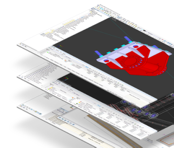
- Visualization of the entire connection in the view window

RF-/JOINTS Steel - Tower | Input
After you have selected the joint type, the connection category, and the design standard in the first input window, you can define the node to be imported from RFEM/RSTAB and to be used for the design of the joint in Window 1.2. Optionally, you can define the connection geometry manually.
In the other input windows, you can then define the parameters of the connection, such as The loading is imported from RFEM/RSTAB or, in the case of manual joint definition, loads are entered.

RF-/JOINTS Steel - Tower | Design
After the calculation, RF-/JOINTS Steel - Column Base displays the following design results:
- Net section design
- Bearing resistance design
- Shear
- Block shear resistance
- Sliding

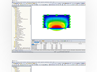
RF-/JOINTS Steel - Tower | Results
At first, the governing joint designs are arranged in groups and displayed with the basic geometry of the joint in the first result window. In the other result tables, you can see all fundamental design details such as the bearing resistance, shearing, sliding, and others.
Dimensions, material properties, and welds important for the connection construction are displayed immediately and can be printed directly. It is possible to visualize the connections in RF-/JOINTS Steel - Tower or in the RFEM/RSTAB model.
All graphics can be included in the RFEM/RSTAB printout report or printed directly. Due to the scaled output, an optimal visual check is possible as early as in the design phase.

.png?mw=192&hash=f63e4a3f1836233005de32f60201d5392e507cf1)
Calculate Your Price
The price is valid for United States. Prices are only valid for the software usage in United States. You can get exact prices after signing in. Please log on to your account at Dlubal Software to generate an updated quote.

Implemented Standards for Reinforced Concrete Design
Standards for Concrete Design
Annexes for EN 1992-1-1


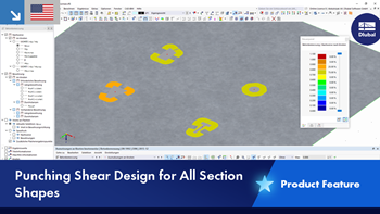


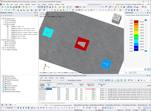
Do you have individual column sections and angled wall geometries, and need punching shear design for them?
No problem. In RFEM 6, you can perform punching shear design not only for rectangular and circular sections, but for any cross-section shape.
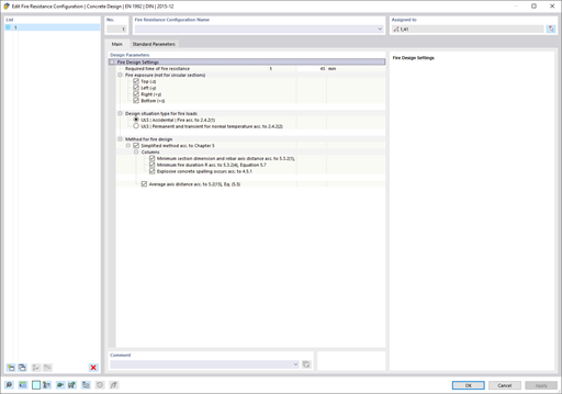
The Concrete Design add-on provides you with the option to perform the simplified fire resistance design according to EN 1992‑1‑2 for columns (Section 5.3.2) and beams (Section 5.6).
The following design checks are available for the simplified fire resistance design:
- Columns: Minimum cross-sectional dimensions for rectangular and circular sections according to Table 5.2a as well as Equation 5.7 for calculating time of fire exposure
- Beams: Minimum dimensions and center distances according to Table 5.5 and Table 5.6
You can determine the internal forces for the fire resistance design according to two methods.
- 1 Here, the internal forces of the accidental design situation are included directly into the design.
- 2 The internal forces of the design at normal temperature are reduced by the factor Eta,fi (ηfi), then used in the fire resistance design.
Furthermore, it is possible to modify the axis distance according to Eq. 5.5.
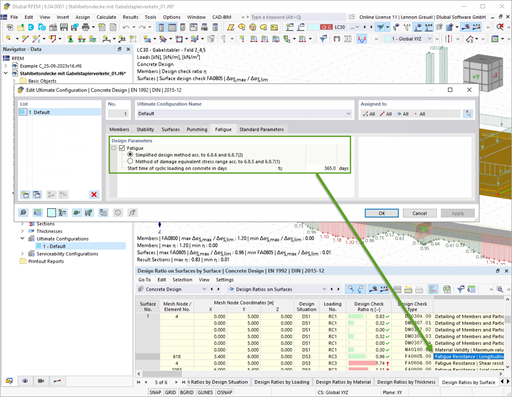
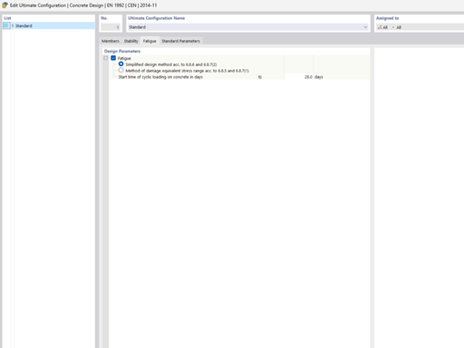
With the Concrete Design add-on, you can perform the fatigue design of members and surfaces according to EN 1992‑1‑1, Chapter 6.8.
For the fatigue design, you can optionally select two methods or design levels in the design configurations:
- Design Level 1: Simplified design according to 6.8.6 and 6.8.7(2): The simplified design is performed for frequent action combinations according to EN 1992‑1‑1, Chapter 6.8.6 (2), and EN 1990, Eq. (6.15b) with the traffic loads relevant in the serviceability state. A maximum stress range according to 6.8.6 is designed for the reinforcing steel. The concrete compressive stress is determined by means of the upper and lower allowable stress according to 6.8.7(2).
- Design Level 2: Design of damage equivalent stress acc. to 6.8.5 and 6.8.7(1) (simplified fatigue design): The design using damage equivalent stress ranges is performed for the fatigue combination according to EN 1992‑1‑1, Chapter 6.8.3, Eq. (6.69) with the specifically defined cyclic action Qfat.
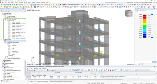
The Concrete Design add-on allows you to perform the seismic design of reinforced concrete members according to EC 8. This includes, among other things, the following functionalities:
- Seismic design configurations
- Differentiation of the ductility classes DCL, DCM, DCH
- Option to transfer the behavior factor from a dynamic analysis
- Check of the limit value for the behavior factor
- Capacity design checks of "Strong column - weak beam"
- Detailing and particular rules for curvature ductility factor
- Detailing and particular rules for local ductility


