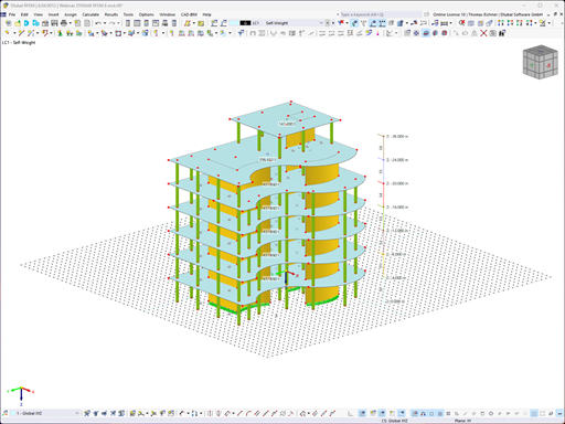
It is possible to selectively display or hide various objects such as nodes, members, supports, and others. The model can be dimensioned by using lines, arcs, inclinations, or height elevations. Freely created guidelines, sections, and comments facilitate the input and evaluation. You can also display or hide the guide objects individually.
![KB 001880 | Design of Cable Structures in RFEM 6 and RSTAB 9](/en/webimage/049985/3840051/Seil_QS_EN.png?mw=512&hash=83dd891c6124be9c686441c4b37fe92db2c2062d)
In this article, you will learn how to model and design cable structures in RFEM 6 or RSTAB 9.
![KB 001879 | Influence of Bending Stiffness of Cables](/en/webimage/049953/3835546/Seil.png?mw=512&hash=83e64fde3c3d0a1d2649d8e64587b93f4ab71876)
This article describes and explains the influence of bending stiffness of cables on their internal forces. Furthermore, the text provides information on how this influence can be reduced.
![Building Overview (KB1866)](/en/webimage/046746/3676167/KB1866_image01_en_Model.png?mw=512&hash=18feed6e03b6c09c60d7e29dc96041d95c24997b)
To evaluate whether it is also necessary to consider the second-order analysis in a dynamic calculation, the sensitivity coefficient of interstory drift θ is provided in EN 1998‑1, Sections 2.2.2 and 4.4.2.2. It can be calculated and analyzed using RFEM 6 and RSTAB 9.
![Reduction of Building to Cantilever Structure The individual mass points represent stories. The deflection due to the normal compression forces shown in (a) is (b) converted into equivalent moments of displacement or shear forces (KB1867)](/en/webimage/046751/3675982/KB1867_image01_building_replacement_system_as_cantilever.png?mw=512&hash=2810652c31c299316a7e4564086f5e5f9b5889b2)
For the ultimate limit state design, EN 1998‑1, Sections 2.2.2 and 4.4.2.2 require a calculation considering the second‑order theory (P‑Δ effect). This effect may be neglected only if the interstory drift sensitivity coefficient θ is less than 0.1.
![Feature 002823 | Generate Bracing in Cells](/en/webimage/050459/3889302/1.png?mw=512&hash=9d7f6c198b6d4ae6ee8f2fa8bca75f85579e14c9)
The "Bracing in Cells" function allows you to generate diagonal bracing with just a few clicks. You can find this feature under Tools → Generate Model – Members → Bracing in Cells.
![Feature 002819 | Flow Field Quantities](/en/webimage/050342/3881104/1.png?mw=512&hash=9d7f6c198b6d4ae6ee8f2fa8bca75f85579e14c9)
In RFEM and RSTAB, you can visualize the flow field quantities of pressure, velocity, turbulence kinetic energy, and turbulence dissipation rate for the wind simulation.
The clipping planes are aligned with the respective wind direction.
![Feature 002817 | Output of Formulas by AI Chatbot Mia](/en/webimage/050182/3885645/50182.png?mw=512&hash=ebd63d5d077338e44649f074b9a002a70ae5b96b)
Are you looking for a formula relevant for your structural design? Just ask our AI chatbot Mia!
Mia shows you the right formula, with explanations, if necessary.
![Feature 002807 | 3D Display of FSM Results](/en/webimage/049281/3861162/2024-05-01_10-32-55.png?mw=512&hash=2377d291bc20ac3d78d617b50c131614e99ac6f7)
In the "Edit Section" dialog box, you can display the buckling shapes of the Finite Strip Method (FSM) as a 3D graphic.